A Gotek USB floppy emulator is an excellent replacement for the aging floppy drive in a Yamaha VL1. Unfortunately, a conventional Gotek installation in the VL1 often uses a workaround that sacrifices density select in order to preserve disk-change detection.
After some experimentation, I found a straightforward solution. By running one additional wire from the Gotek’s JC signal pad to the 26-pin adapter and installing a small custom modification to the FlashFloppy firmware, the VL1 can retain both disk-change detection and density select.
Important: This modification is specifically documented for the Yamaha VL1 and VL1-m using the 34-to-26-pin adapter described below. I can’t guarantee this will work on other similar 26-pin Yamaha devices.
The Problem With a Standard Gotek Installation
The Yamaha VL1’s original floppy drive uses a 26-pin interface. In addition to the usual floppy-drive signals, the VL1 expects separate signals for drive readiness, disk change, and media density.
FlashFloppy normally handles configurable output signals through pins 2 and 34. These signals can be configured through FF.CFG. In this particular application, however, those connections are used to preserve disk readiness and media density.
The practical result is a Gotek that may initially read a disk image but does not tell the VL1 when another image has been selected. The keyboard continues behaving as though the previous disk were inserted. Alternatively, a configuration that restores disk change may lose proper selection between double-density and high-density media.
Some enterprising users have taken the customizable pin 2, which is normally used for density signals, and physically connected it to pin 6 of the 26-pin header. In other words, they sacrificed the density-select output so that disk-change detection would work correctly.
The solution is to use the Gotek’s otherwise-unused JC signal pad as an additional disk-change output. The custom FlashFloppy fork linked below adds exactly that behavior.
What You Will Need
- A standard 34-pin Gotek floppy emulator
- FlashFloppy already installed on the Gotek
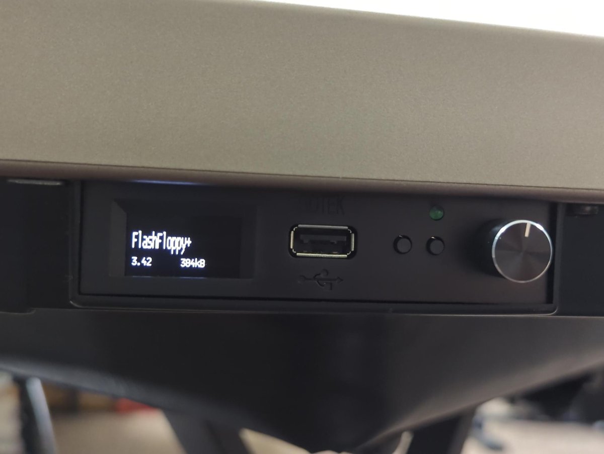
- An OLED display and rotary encoder, if using my supplied configuration without alteration
- A FlexiDrive 34-to-26-pin P1.25 adapter
- One small wire with a female end, such as a common multicolored Arduino wire. The other end will be snipped.
- A FAT32-formatted USB stick
- My VL1 FlashFloppy configuration and firmware package
The FlexiDrive adapter is sold as a general 34-to-26-pin floppy adapter, and its compatibility list specifically includes the Yamaha VL1 and VL1-m. It also provides a conveniently accessible 26-pin header for the additional disk-change connection. Because it does not require the extra cabling used by some adapters, it is slim and well suited to this installation.
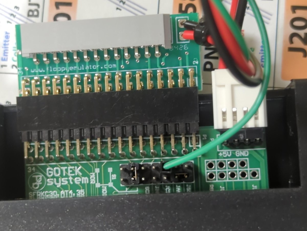
Before Beginning
- Turn off and unplug the VL1 before opening it or changing any connections.
- Confirm the orientation and numbering of the 26-pin connector before attaching the jumper.
- Do not place a conventional shorting jumper across both JC pads.
- Connect only the JC signal side to the appropriate adapter pin.
- Secure the wire so that it cannot move, contact another pin, or become trapped during reassembly.
Pin numbering is particularly easy to reverse when a connector is viewed from the cable side rather than the pin side. Use the photographs as an orientation guide, but verify the numbering on your own adapter before applying power.
Step 1: Add the JC Disk-Change Wire and Set Jumpers
Add JC Disk-Change Wire
Locate the position marked JC on the Gotek circuit board. JC is normally associated with selecting an IBM PC-style floppy interface, but the custom firmware repurposes its microcontroller signal pad as an active-low disk-change output.
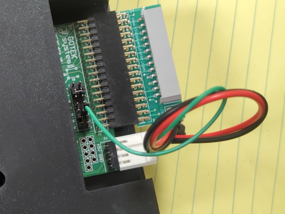
Attach one end of a single wire to the JC signal pad only. Do not short the two JC pads together.
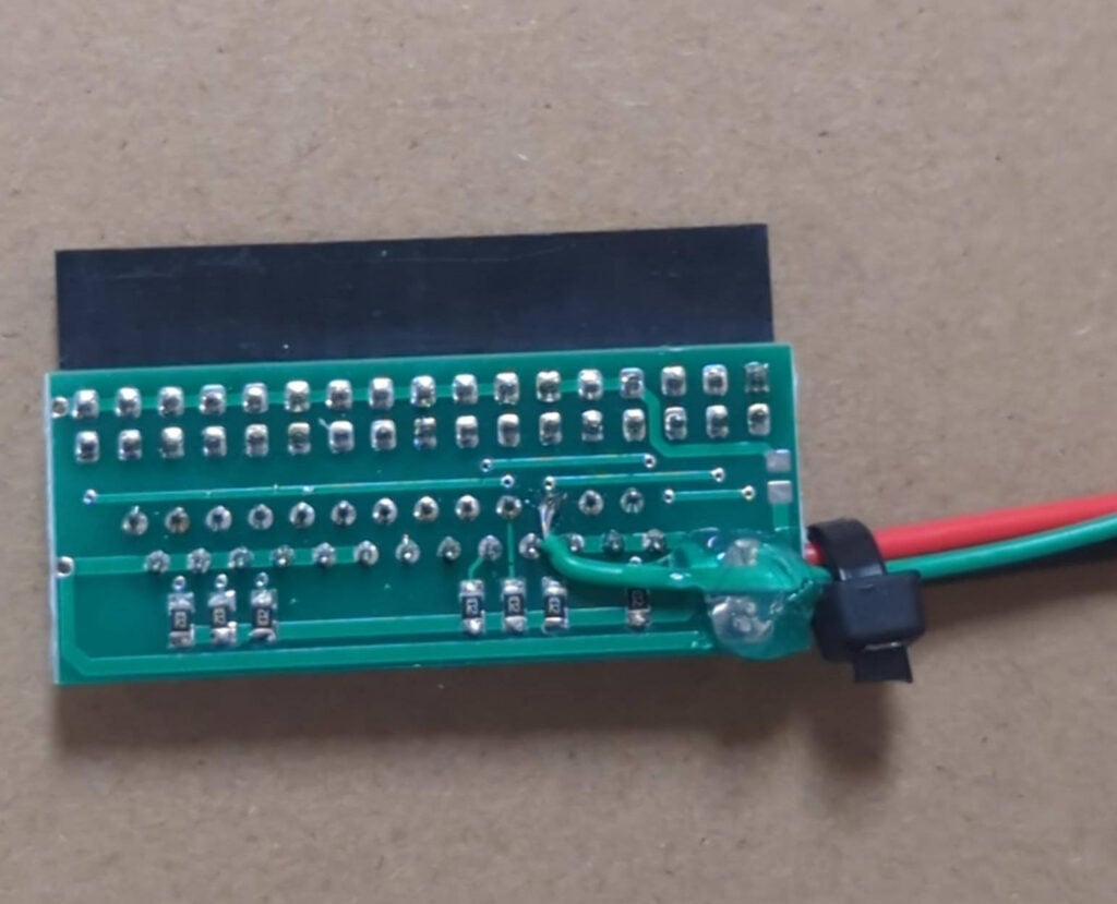
Connect the other end of the wire to pin 6 on the 26-pin header of the FlexiDrive adapter.
Pin-number clarification: The firmware source refers to the disk-change connection as pin 4 on the Gotek-side floppy header. With the FlexiDrive adapter used here, the convenient connection point is pin 6 on the adapter’s 26-pin header. These instructions assume this particular adapter and wiring arrangement.
I used an ordinary female Arduino wire. I cut off the connector at the other end, stripped the wire, and soldered it to pin 6 on the 26-pin header. Once connected, route and secure the wire so that it cannot fall off or contact adjacent pins.
Set Jumpers
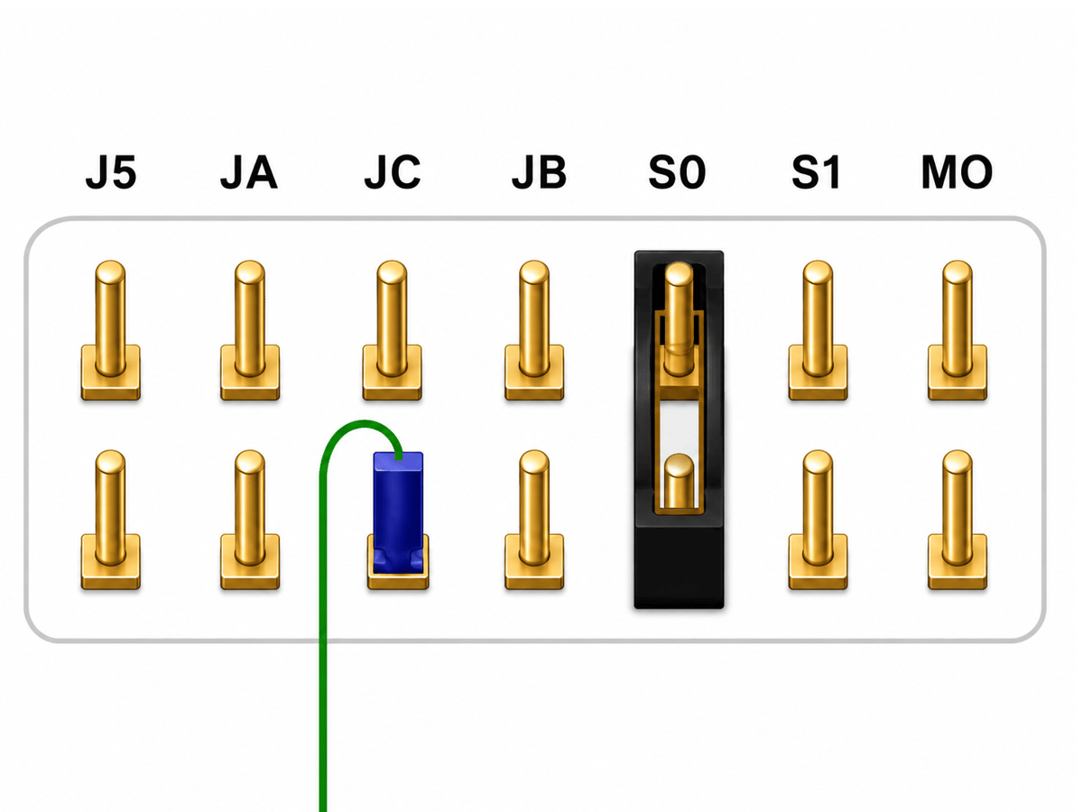
For the VL1 to identify the drive, it needs to be configured as S0, not S1. There is a diagram of the proper jumper and wire position below. Most Goteks come with the jumper in the S1 position, which will not work. If any other jumpers are present, remove them.
Step 2: Install the Gotek and Adapter
Connect the Gotek’s standard 34-pin floppy header to the FlexiDrive adapter. Connect the VL1’s original 26-pin ribbon cable to the adapter’s 26-pin P1.25 connector.
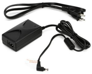
Also connect power to the Gotek using the power connector included with your adapter. Before mounting everything permanently, make sure that the adapter and cables are oriented correctly and that no exposed contacts can touch the VL1 chassis.
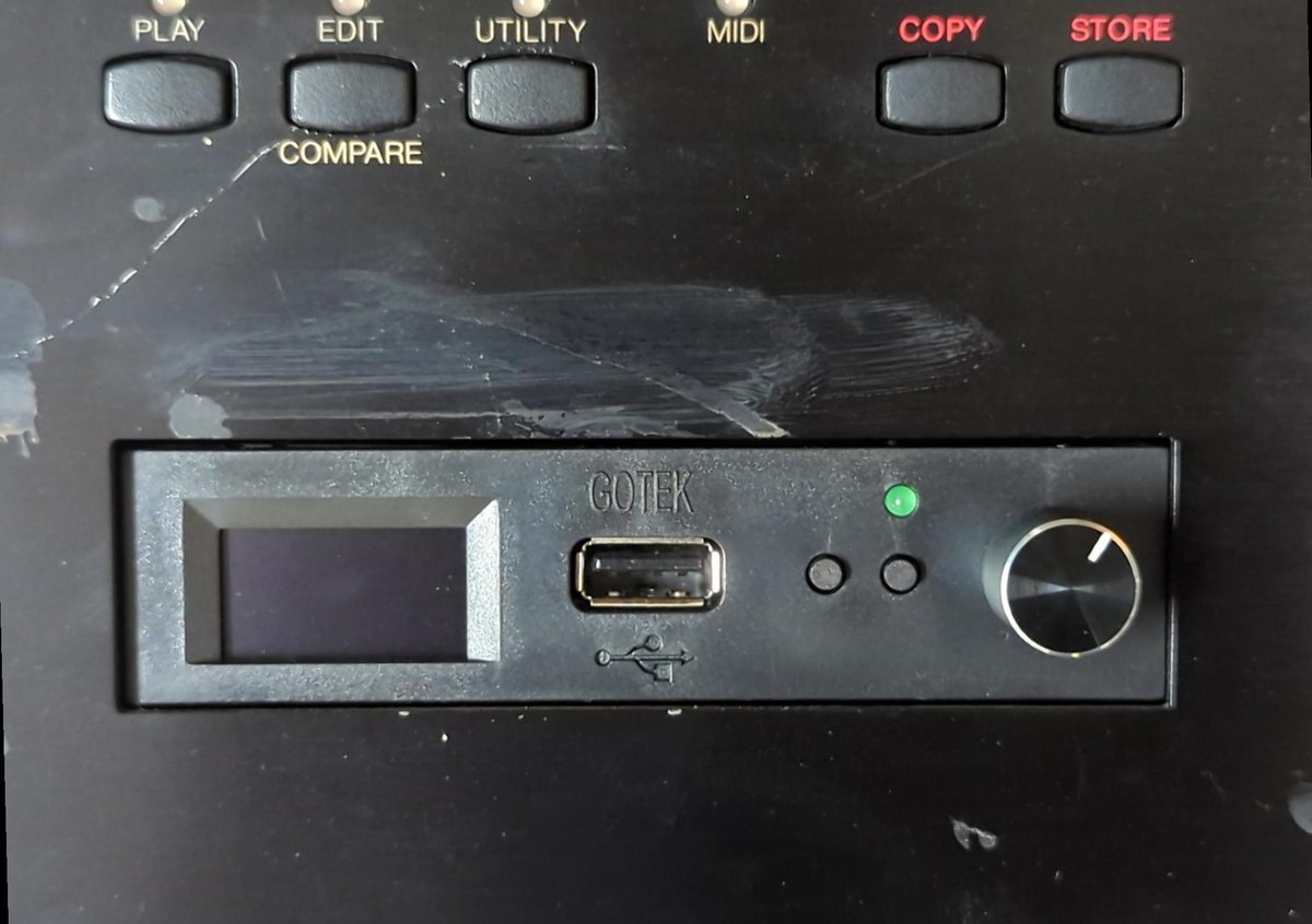
Step 3: Install the Custom FlashFloppy Firmware
The additional wire will not do anything with ordinary FlashFloppy firmware. The Gotek must also be running the custom fork that outputs the disk-change signal through JC.
If your Gotek already has FlashFloppy installed, installing the modified build is a normal USB firmware update.
Prepare the USB Stick
- Format a USB stick as FAT32 if it is not already FAT32.
- Remove any older
.updfiles from the root of the USB stick. - Copy the supplied custom firmware
.updfile to the root of the USB stick. You can download the latest version I compiled from my shared folder, or you can download it from my fork on GitHub here. - Copy
FF.CFGand at least one.IMGdisk-image file to the USB stick. Both are available at the download link above. PlaceFF.CFGin the root of the USB stick. If the stick already contains anFFfolder, placeFF.CFGinside that folder instead, because FlashFloppy will not search the root when anFFfolder exists.
Perform the Firmware Update
- Turn off the Gotek by powering off the VL1.
- Insert the USB stick.
- Hold both Gotek navigation buttons while turning the VL1 back on. On an enhanced Gotek, press and hold the rotary encoder instead.
- When the display enters the update mode, release the buttons or encoder.
- The firmware should install automatically, after which the Gotek will restart.
A Gotek that already has FlashFloppy is strongly recommended because its bootloader makes this update straightforward. A new Gotek still running factory firmware must first be programmed with FlashFloppy using the normal initial-installation procedure.
This firmware is an unofficial fork of FlashFloppy created specifically for this application. Its source is publicly available in the flashfloppy-vl1-jc-diskchange GitHub repository.
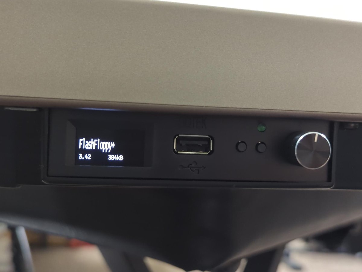
Step 4: Test the Installation
- Turn on the VL1 with the USB stick inserted.
- Select a valid disk image and confirm that the VL1 can read it. I have a blank image file shared along with the
FF.CFGand firmware that you can use to test. - Change to a different image using the Gotek’s encoder or buttons.
- Confirm that the VL1 recognizes the new disk without requiring a restart.
- If available, also test a 720 KB image to confirm that both densities are selected correctly. I have one of those in my shared folder as well.
- Save and reload a small file to verify both read and write operations.
When everything is working correctly, selecting another disk image should behave much like physically ejecting one floppy disk and inserting another. The VL1 should recognize the change, while density select should allow both double-density and high-density images to operate correctly.
Troubleshooting
The VL1 says Disk Not Ready
Confirm that the supplied FF.CFG is present and being loaded.
Check that the drive select jumper is in the S0 position, and not the S1 position.
The Gotek reads the first image but does not recognize disk changes
Confirm that the modified firmware was actually installed.
Confirm that the wire is attached to the JC signal pad rather than the ground side.
Verify the connection to pin 6 on the adapter’s 26-pin header.
Check that the wire has not slipped off either connection.
Make sure an older FF.CFG is not being loaded from an existing FF directory.
The Gotek says Error 34
Error 34 means that FlashFloppy did not find a valid disk-image file.
Confirm that at least one .IMG disk-image file is present on the USB stick.
Try one of the known-good blank images included in the download package.
Make sure the image has been extracted from any ZIP archive.
If the image is present but the error remains, reformat the USB stick as FAT32 or try another USB stick.
The VL1 reports a bad disk or will only use one disk density
Use one of the known-good blank images supplied in the download package.
Confirm that the supplied FF.CFG is present and being loaded.
Verify that the image really is the expected 720 KB or 1.44 MB size.
Recheck the adapter and ribbon-cable orientation.
The firmware update does not start
Make sure the USB stick is formatted as FAT32.
Place the firmware file in the root directory.
Remove unrelated or older .upd files.
Hold both buttons, or the encoder, while power is first applied.
Confirm that the Gotek already has a FlashFloppy bootloader.
Downloads and Source Code
Download Firmware, FF.CFG, and Blank Images
View the Modified Source on GitHub
The download package includes the custom firmware update, the matching FF.CFG, and blank 1.44 MB and 720 KB disk images. The configuration assumes an OLED display and rotary encoder, although the display and control settings can be adjusted for other Gotek hardware.
Contents of FF.CFG
# Yamaha VL1 / VL1-m with FlexiDrive 34-26 P1.25 adapter
# Please note that this FF.CFG does NOT handle disk change behavior.
# You will have to power the device off and back on again after selecting your disk.
# To avoid this, add the custom firmware available here:
# https://github.com/diskchord/flashfloppy-vl1-jc-diskchange

interface = akai-s950
host = pc-dos

# FlexiDrive/VL1 adapter puts density/HD select on 34-pin pin 2.
pin02 = dens

# FlexiDrive/VL1 adapter puts READY on 34-pin pin 34.
pin34 = rdy

# When using custom firmware, the disk change signal is sent over the JC
# pin. However, we can still alter its behavior. The VL1 takes a while to
# acknowledge a disk change. The "step" option keeps the disk change signal
# present until the VL1 responds.
chgrst = step

# You will typically want to write to the disks, so we leave write-protect off.
write-protect = no

nav-mode = nativeCode language: Bash (bash)